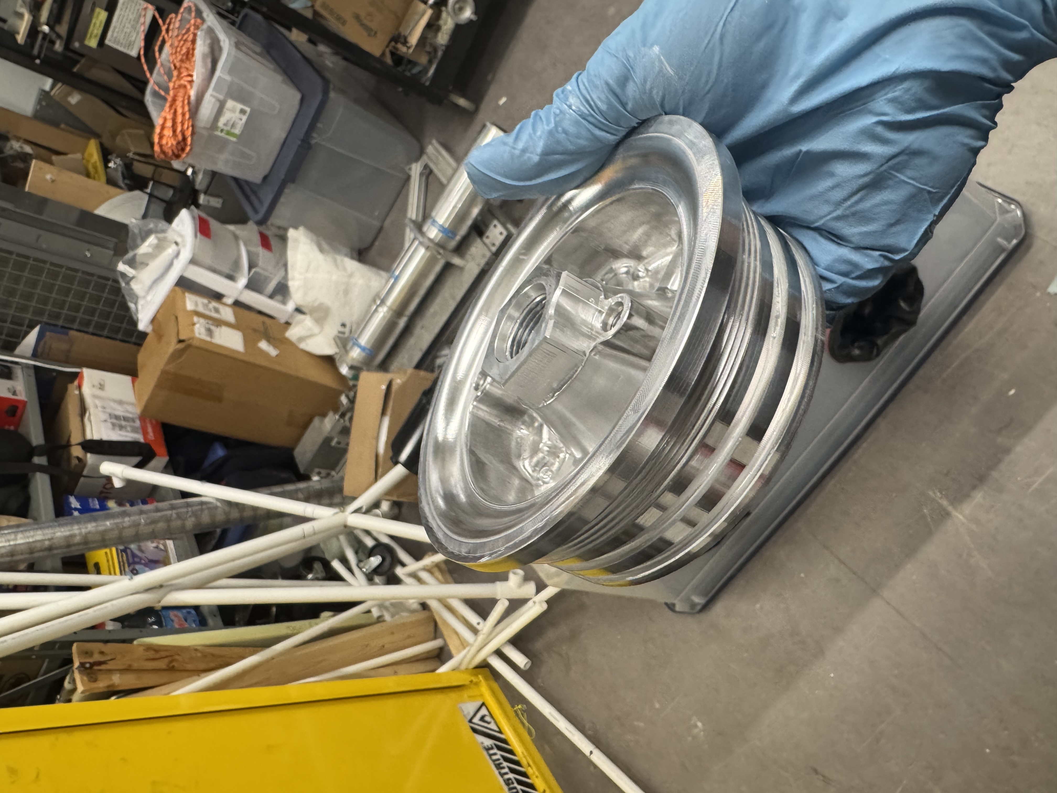
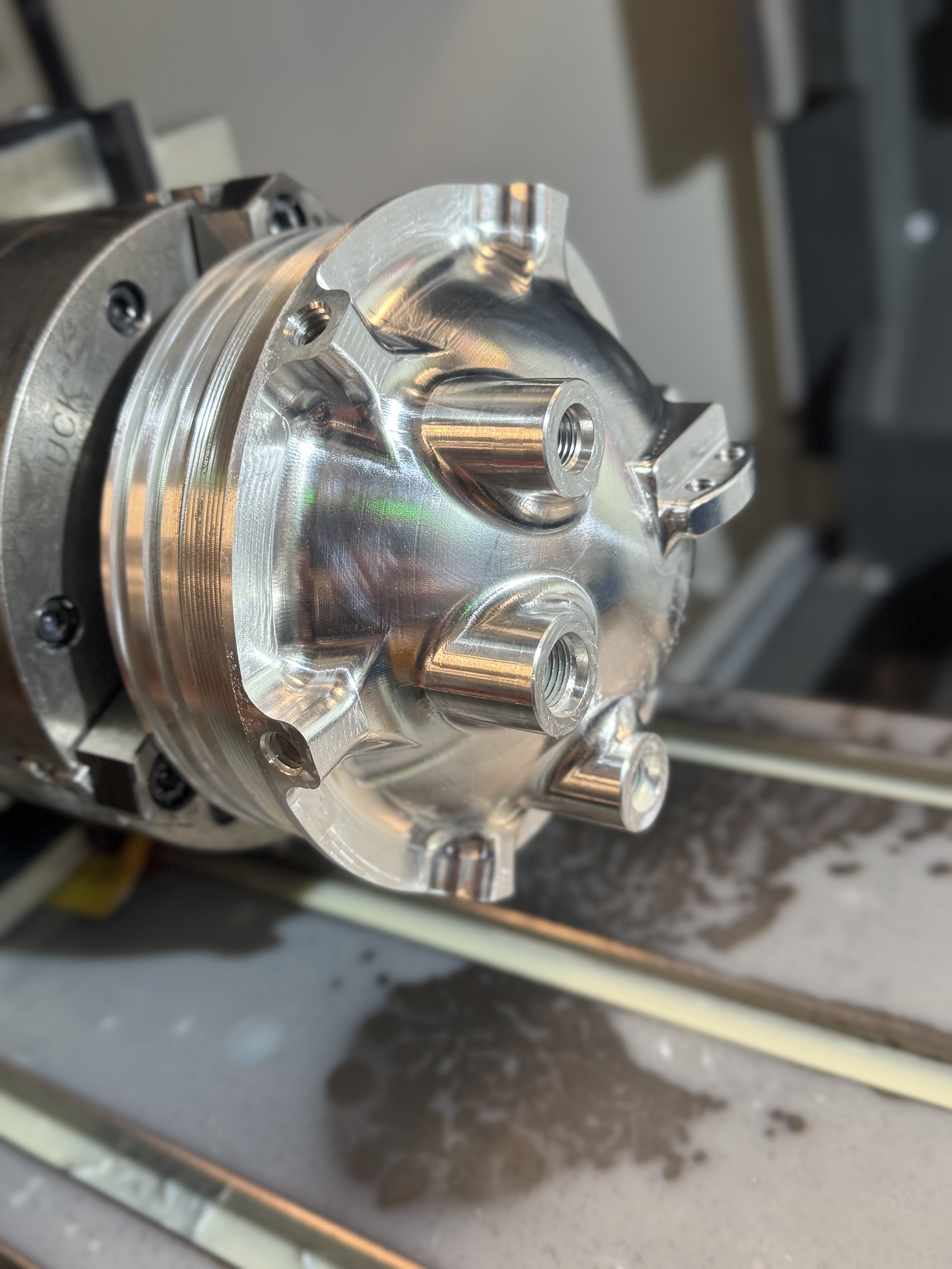
New Injector Body
Freshly machined threaded injector body for our 1385lbf engine. This injector body flew on our rocket during test launch and competition launch.
For the Cornell Rocketry Team, I CNC machined 80 unique components on 3- and 4-axis HAAS mills, accumulating over 275 hours of experience. Every component is a unique challenge and I enjoy trying new techniques and tools that I have picked up from watching way too many machining youtube videos. One of my favorite techniques is using in-process probing to automate the setup process for production runs. .
Freshly machined threaded injector body for our 1385lbf engine. This injector body flew on our rocket during test launch and competition launch.
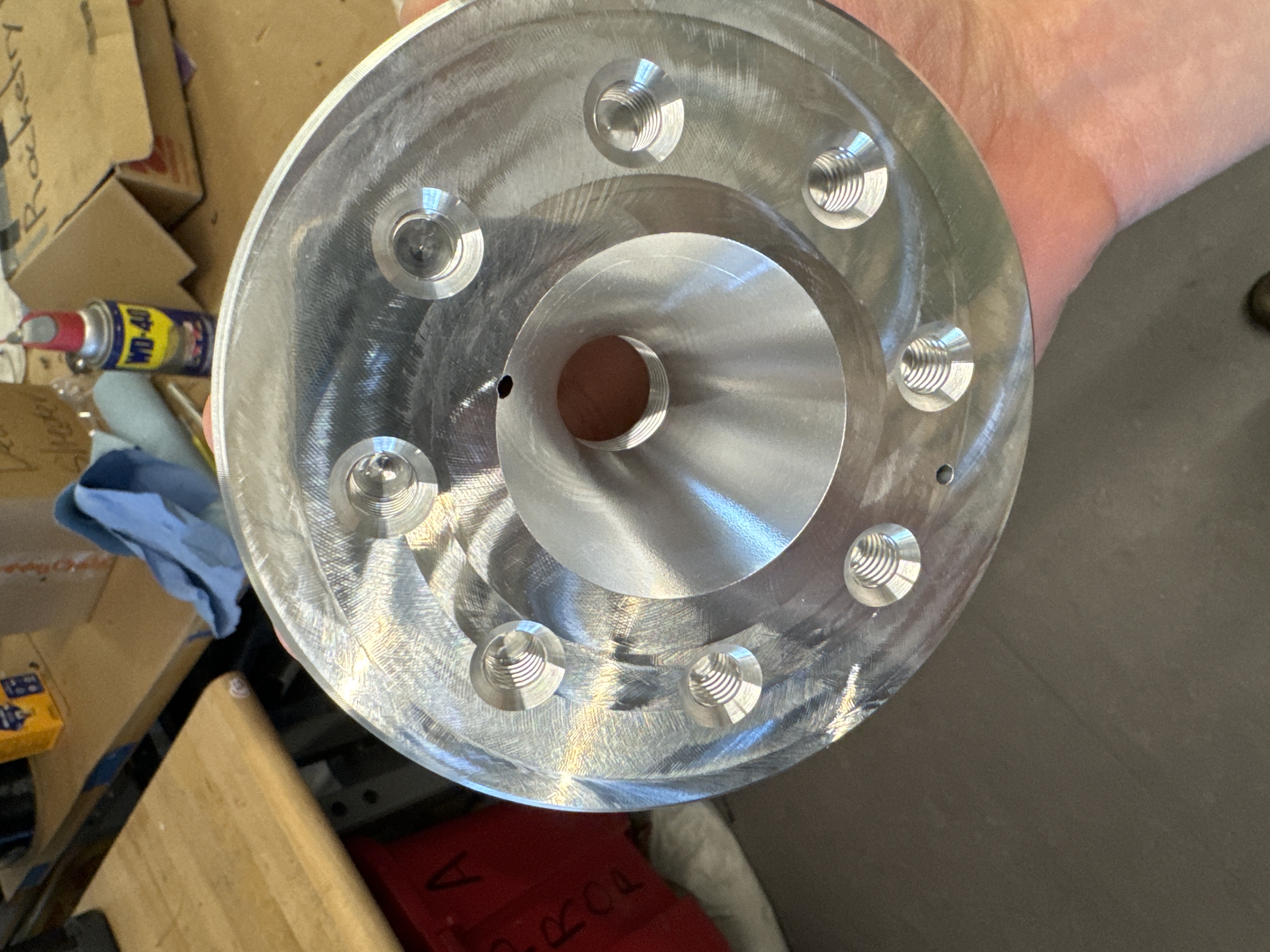
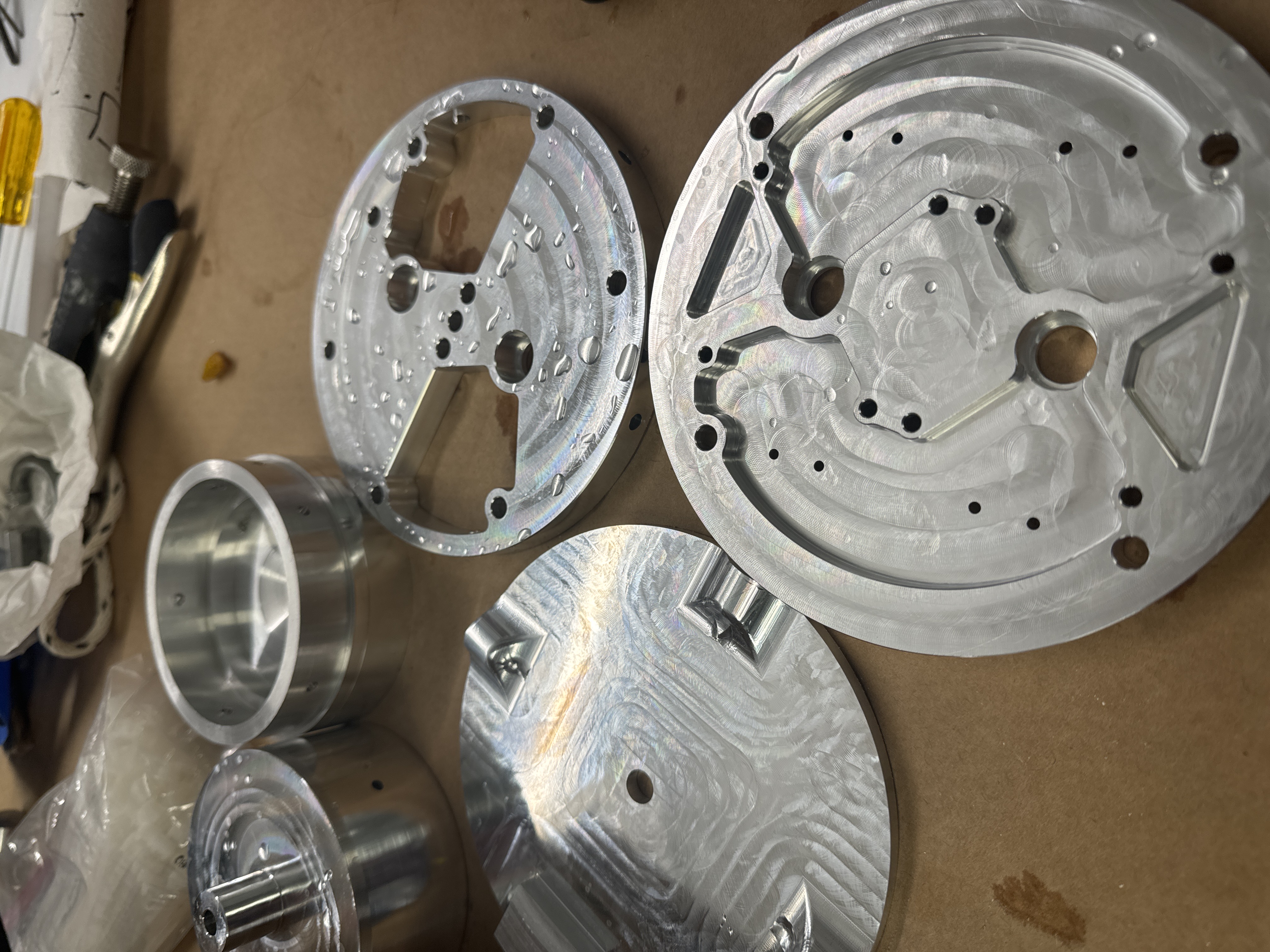
Injector body after setup 1 and setup 2.
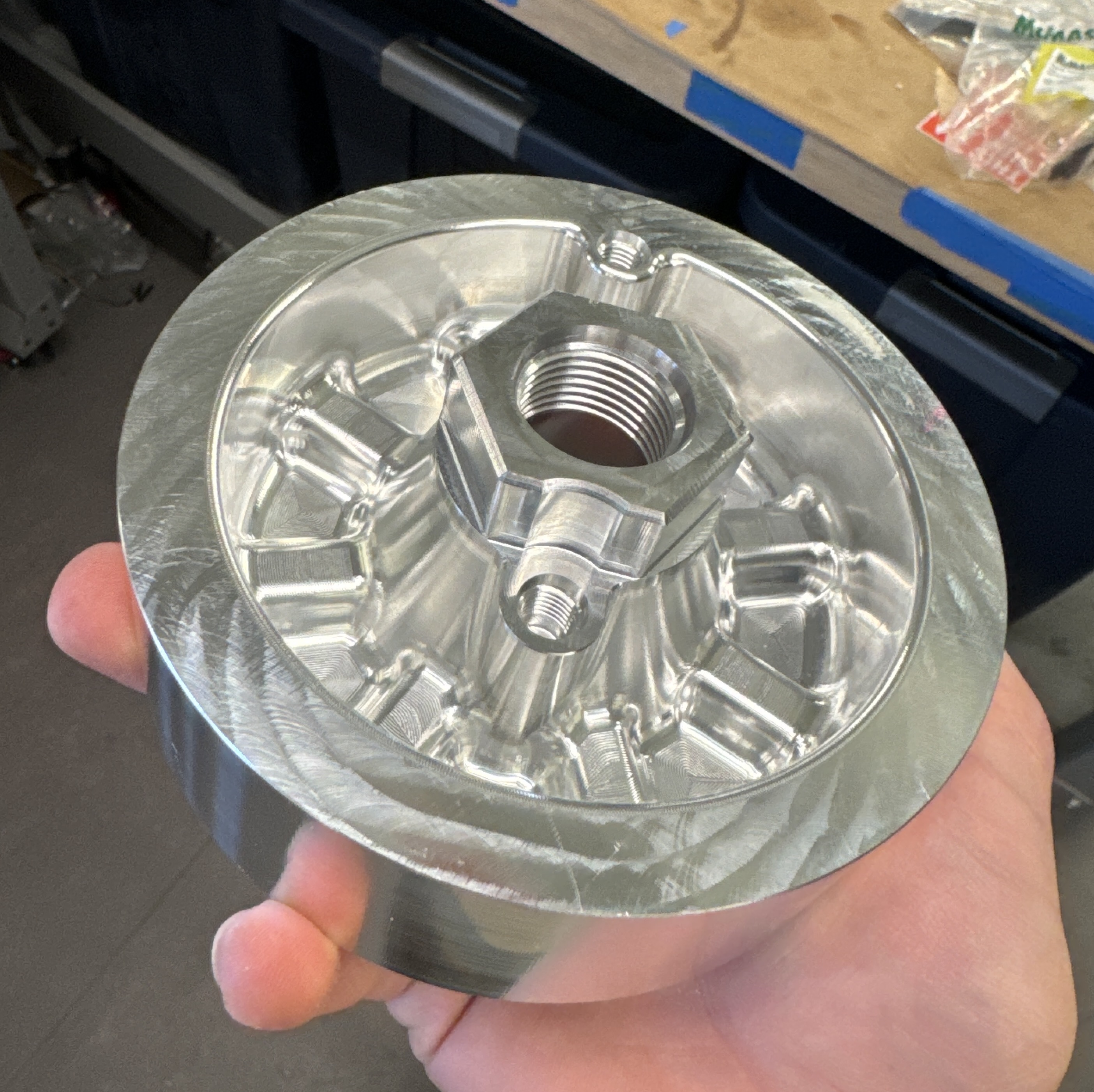
Injector body inner features with Keenserts and nitrous diffuser shown. Keenserts are a massive pain to install, however they are useful here to prevent the threads from stripping out after repeated hot fires and reinstallations of the injector plate.
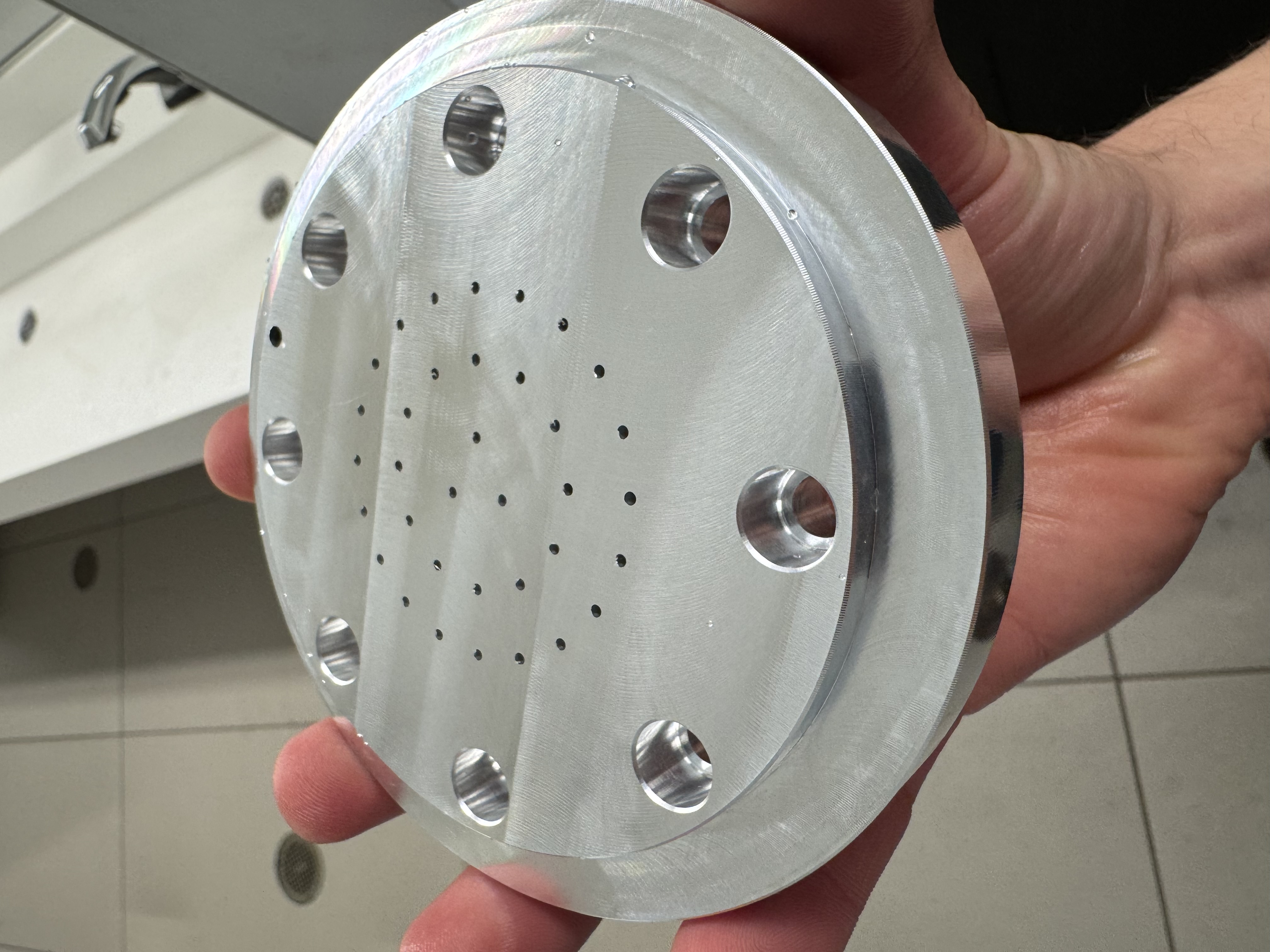
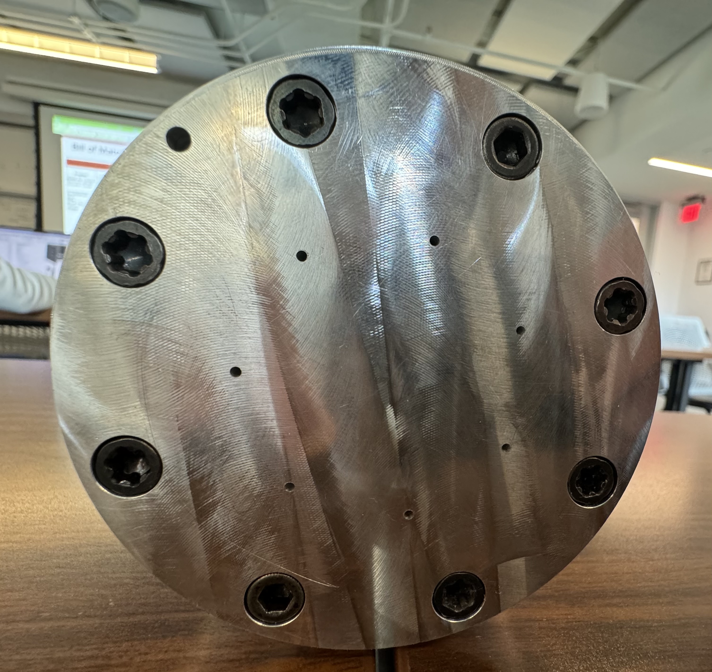
Injector plate hole pattern after precision drilling. It took a lot of trial and error to figure out the correct speeds and feeds for these tiny holes due to their small diameter and large L/D ratio.
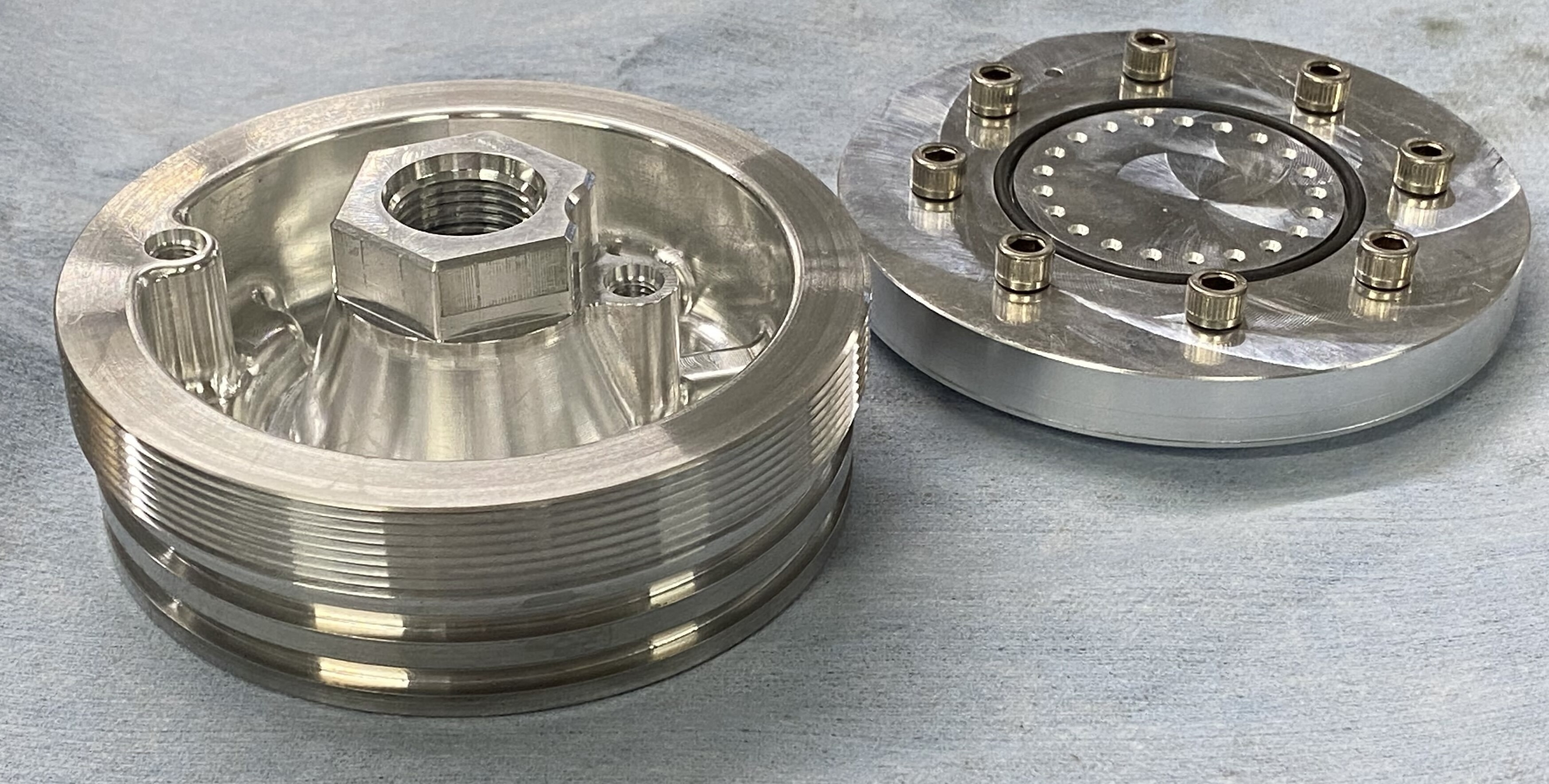
Injector components right before assembly. The injector plate is bolted to the injector body, and seals with a face seal o-ring.
Our initial injector design required several lathe and mill operations for both the body and the plate which was very time consuming. This meant that we could not easily change out our injector plate to try different hole patterns. I designed and machined this injector prototype which features a very simple injector plate design which can be machined in just two quick mill setups on the same machine. This injector was one of my first CNC projects and I learned a lot, including how to make radial grooves on a mill.
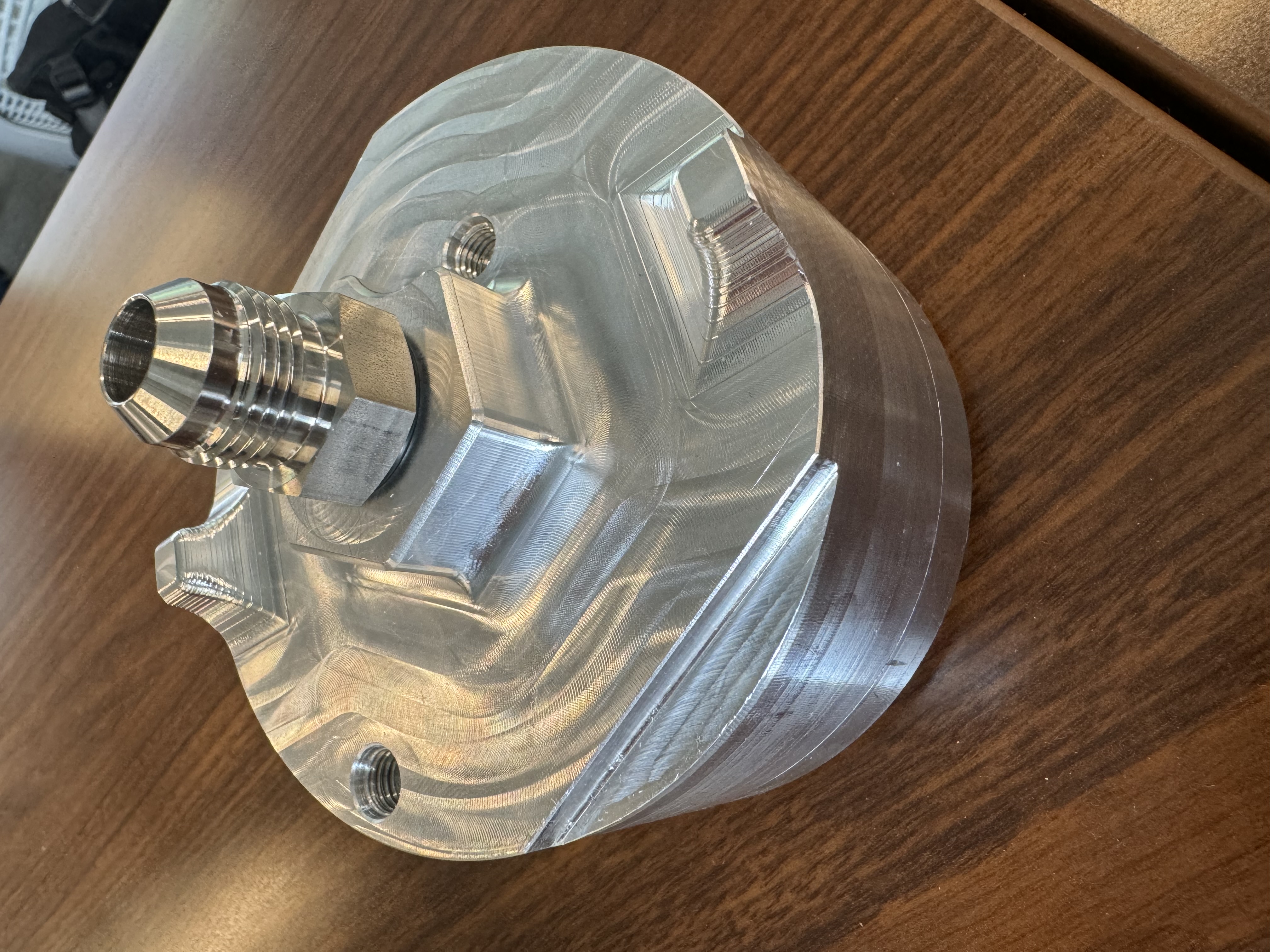
Top view of my prototype injector assembly.
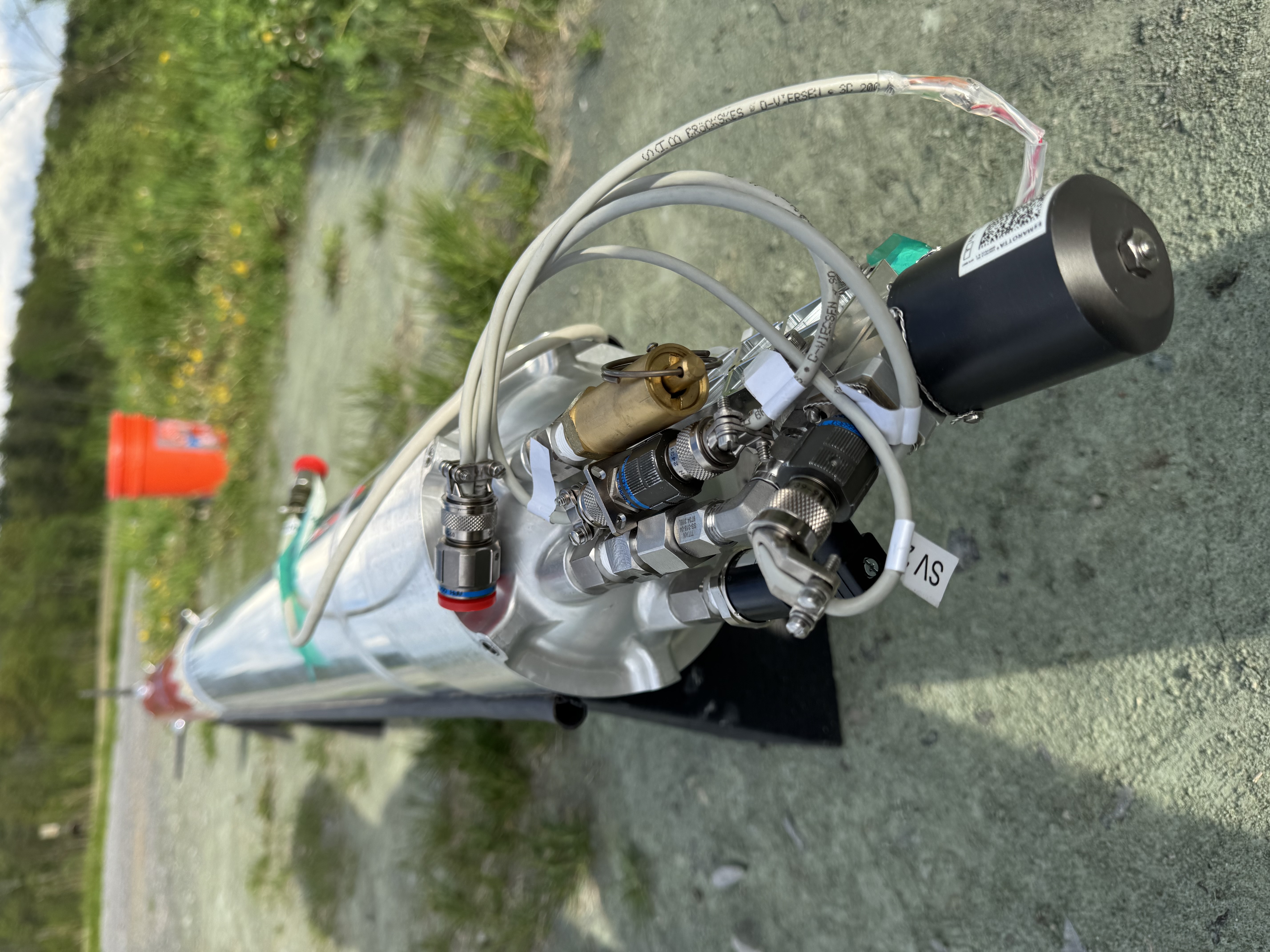
Fully assembled run tank with valve stack and wiring harness installed.
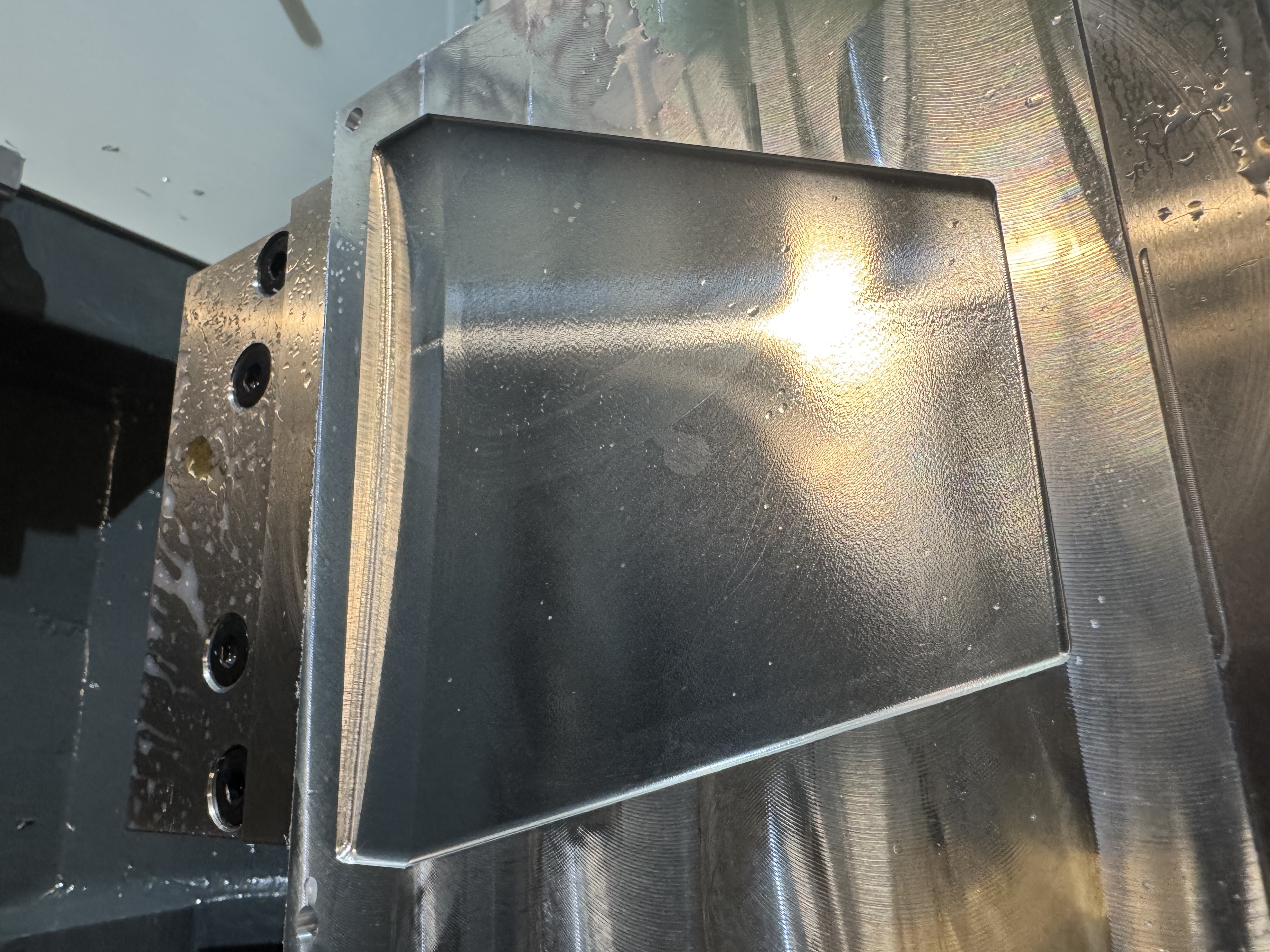
The run tank forward bulkhead was one of the most complicated and challening parts to machine. First, a 6.25" diameter piece of 7075 aluminum is mounted in the HAAS, and the inner cavity is machined out. Then in the same setup, the O ring grooves are cut using a keyseat cutting tool. The keyseat cutter is also used to make the thread relief in preparation for threading the bulkhead. Next, a large threadmill is used to thread the OD of the bulkhead. The threads are then chekced for fit with the run tank casing by carefully screwing in the casing while the bulkhead is still attatched in the vice. If the threads do not fit, it is easy to just take another light pass with the threadmill which can be repeated until the threads fit satisfatctorily. The part is then flipped and carefully placed in the custom soft jaws so that the top can be machined. The top operations have a very long run time due to the high surface finish requirement. The O-boss ports are also machined in this setup. Once the top is finished, the bulkhead can then be mounted in the 4th axis (shown in the picture) for the final operations where the radial holes are drilled and threaded.
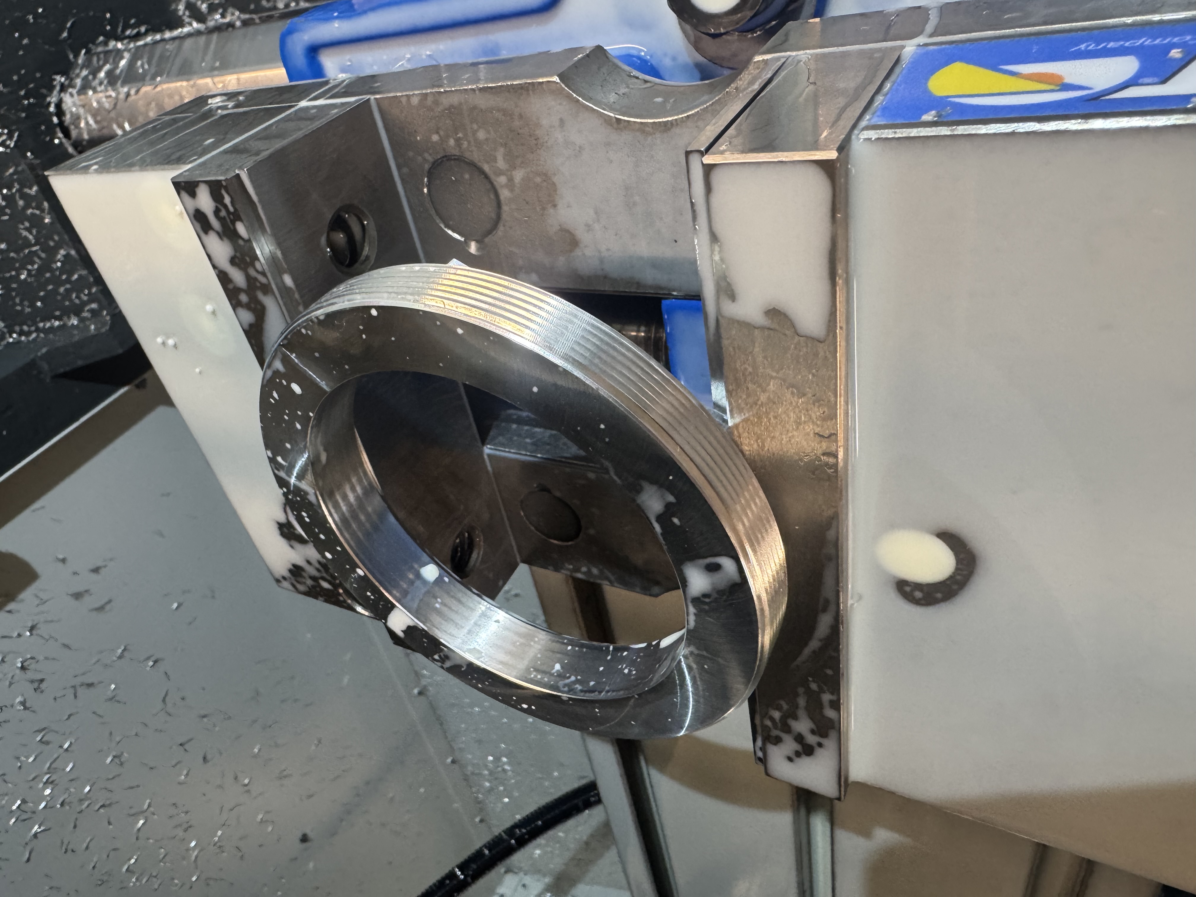
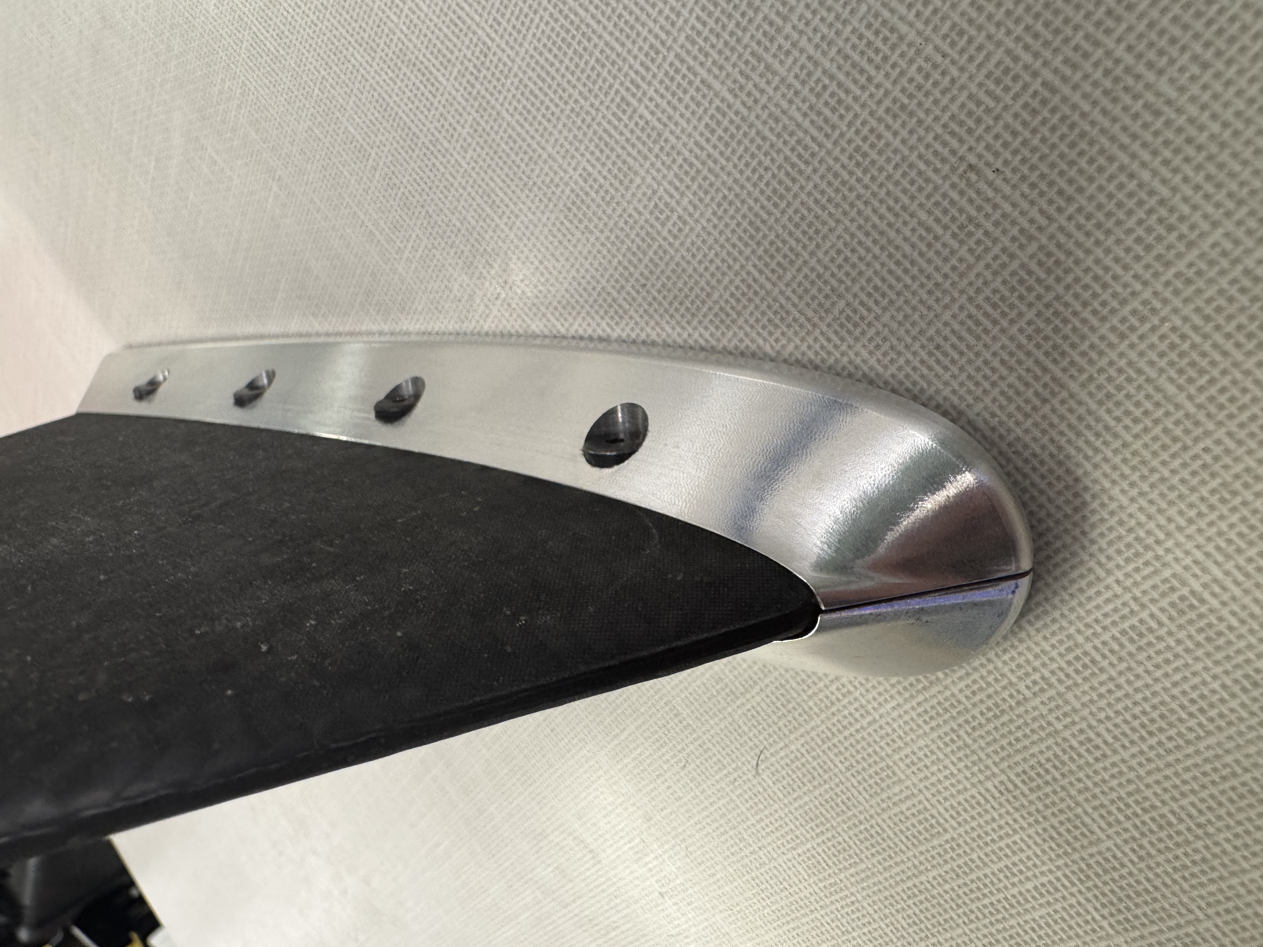
This retention ring is used to retain the graphite+G11 nozzle assembly on our flight scale hybrid engine. I machined this retention ring on the HAAS mill using a very large threadmill. I had to be careful not to use too much vice pressure or the part will deform into an oval after it is removed from the vice and then the threads will gall up.
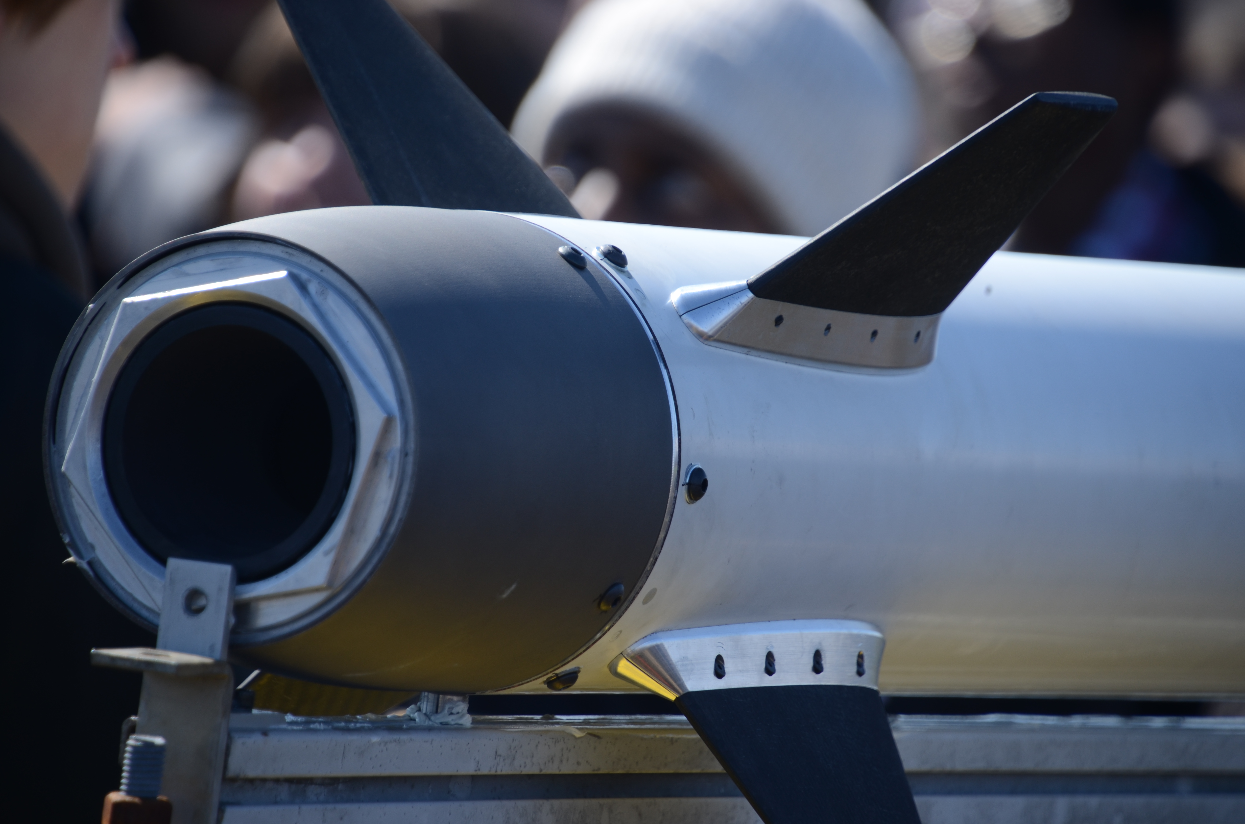
Retention ring shown installed our engine prior to test flight.
Composite fin mould used to make our carbon fiber fins. Achieving a very high quality surface finish was a challenge due to the way the shallow curved surface intersects with tight corners in the edges.
Aluminum fin mounts after finishing. These mounts were quite challenging to machine due to the hole patters on the side and on the bottom of the mounts, along with the lack of flat surfaces for fixturing. This part required two separate custom fixtures and required 3 axis and 4 axis operations. Matthew Checkhlov was the primary machinist on this project, and I helped out by improving the CAM and running several of these mounts.
Machined bracket for our Mechanically Actuated Valve assembly. This was a quick and easy part where I got to play around with rigid tapping.

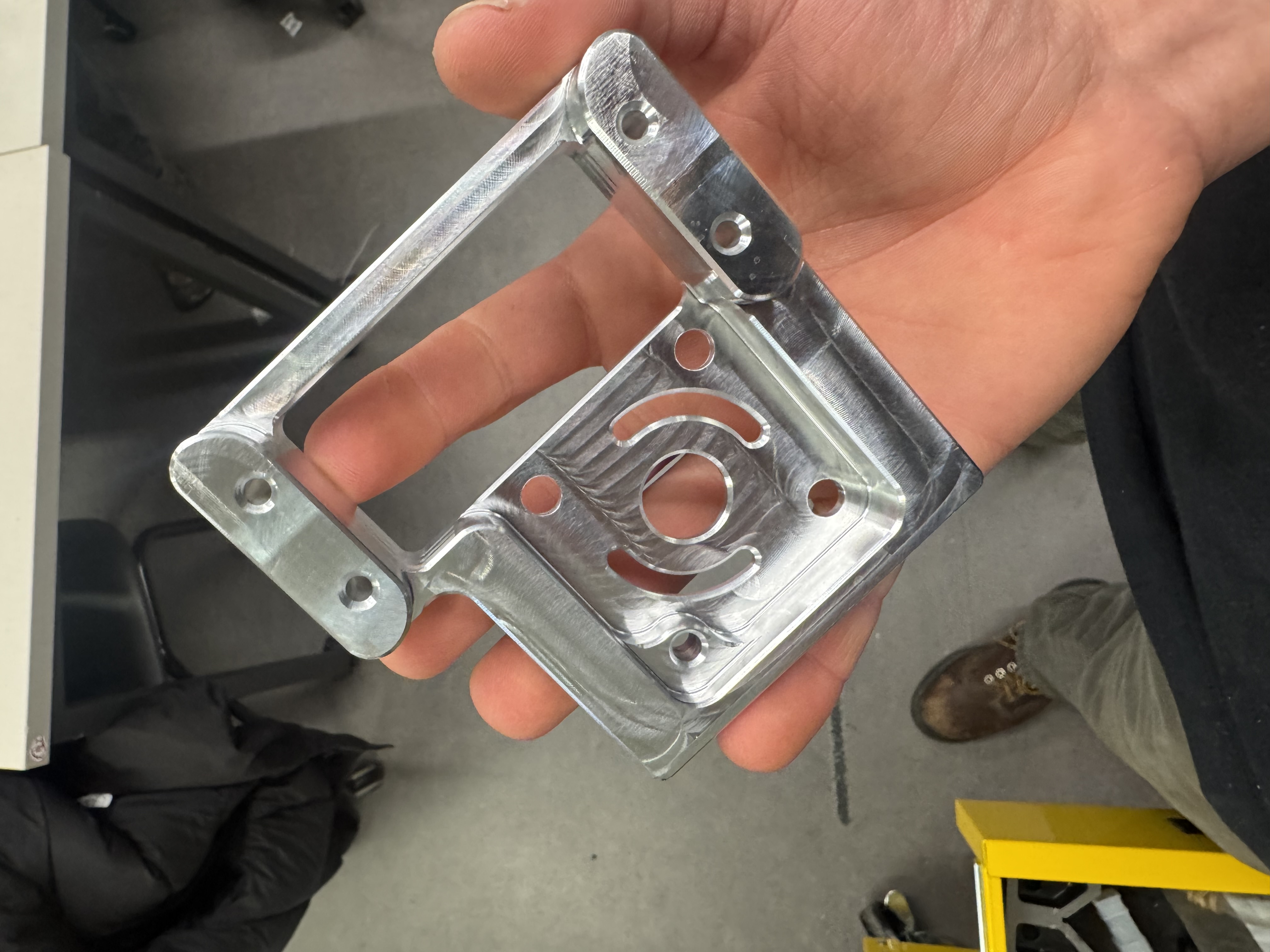
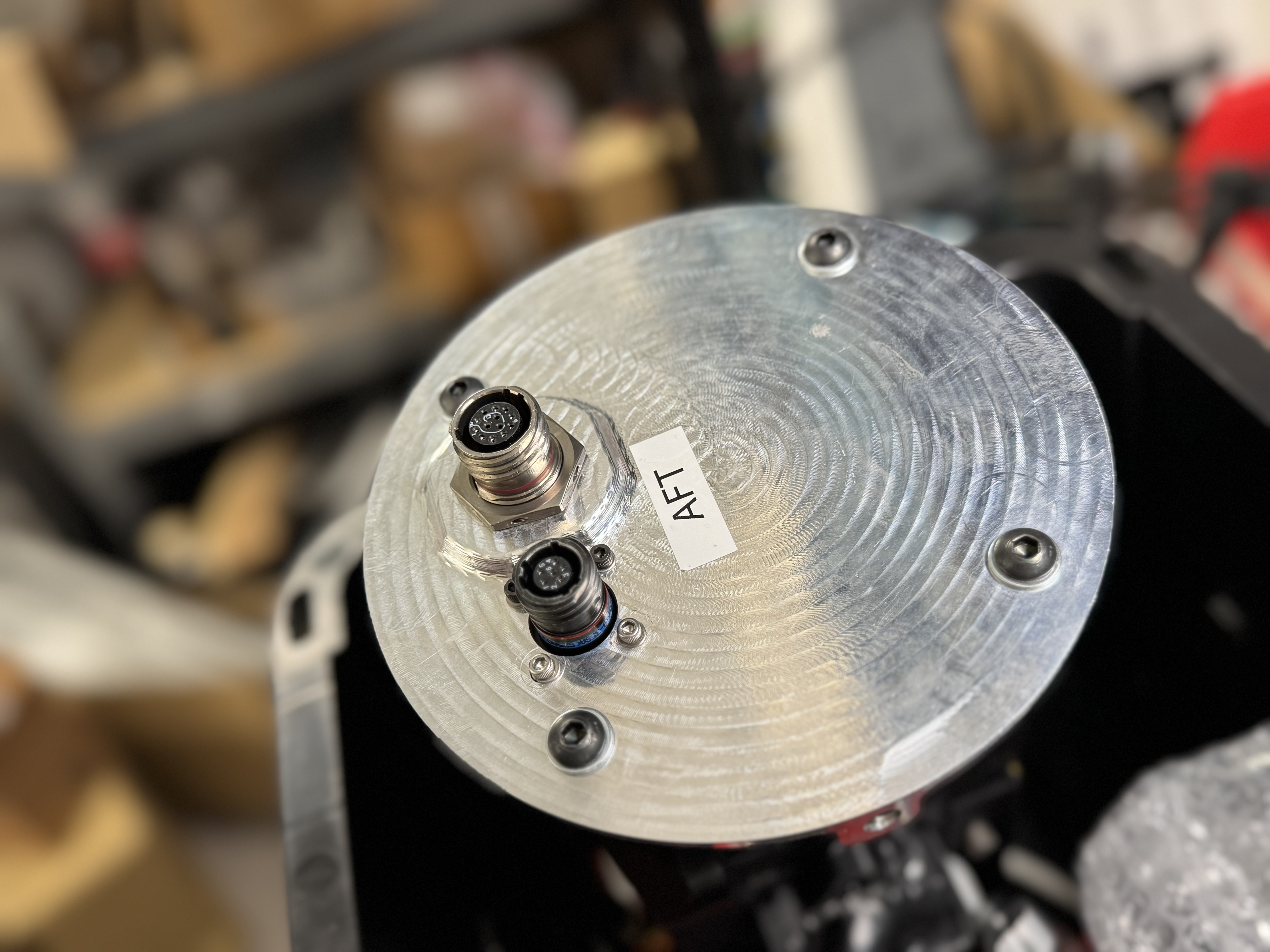
Aft avionics bay hardware post-machining. I designed this bulkhead to secureley mount our aft D38999 connectors to prevent strain on the wires.
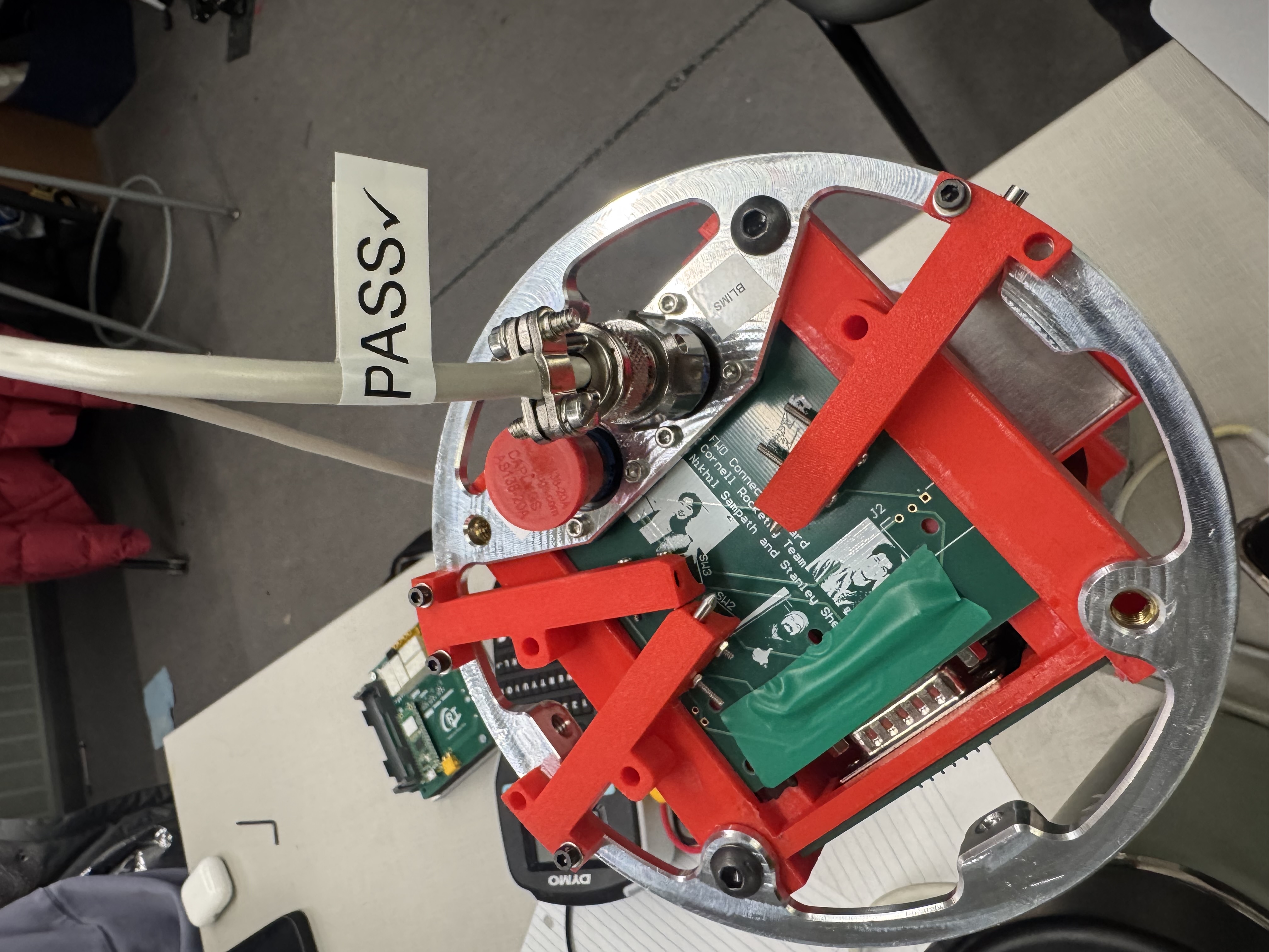
This bulkhead is used to mount our forward D38999 connectors, as well as securing our arming keys and backup flight computer. This part was very thin which was quite difficult to fixture. I designed our avionics bay to be very rapidly installed and removed from our rocket to speed up our assembly process. In previous years the avionics bay took several hours to install due to the poor wiring design and arming key placement. I placed the arming key switches directly on the AV bay so that they could be directly soldered to our avionics boards instead of connected through messy wiring to the airframe as they were in previous years. I secured a sponsorship from Amphenol, who donated several thousand dollars worth of connectors to our team, allowing me design a robust wiring harness which was also incredibly easy to install and remove.
CRT logo engraving on aluminum plate.
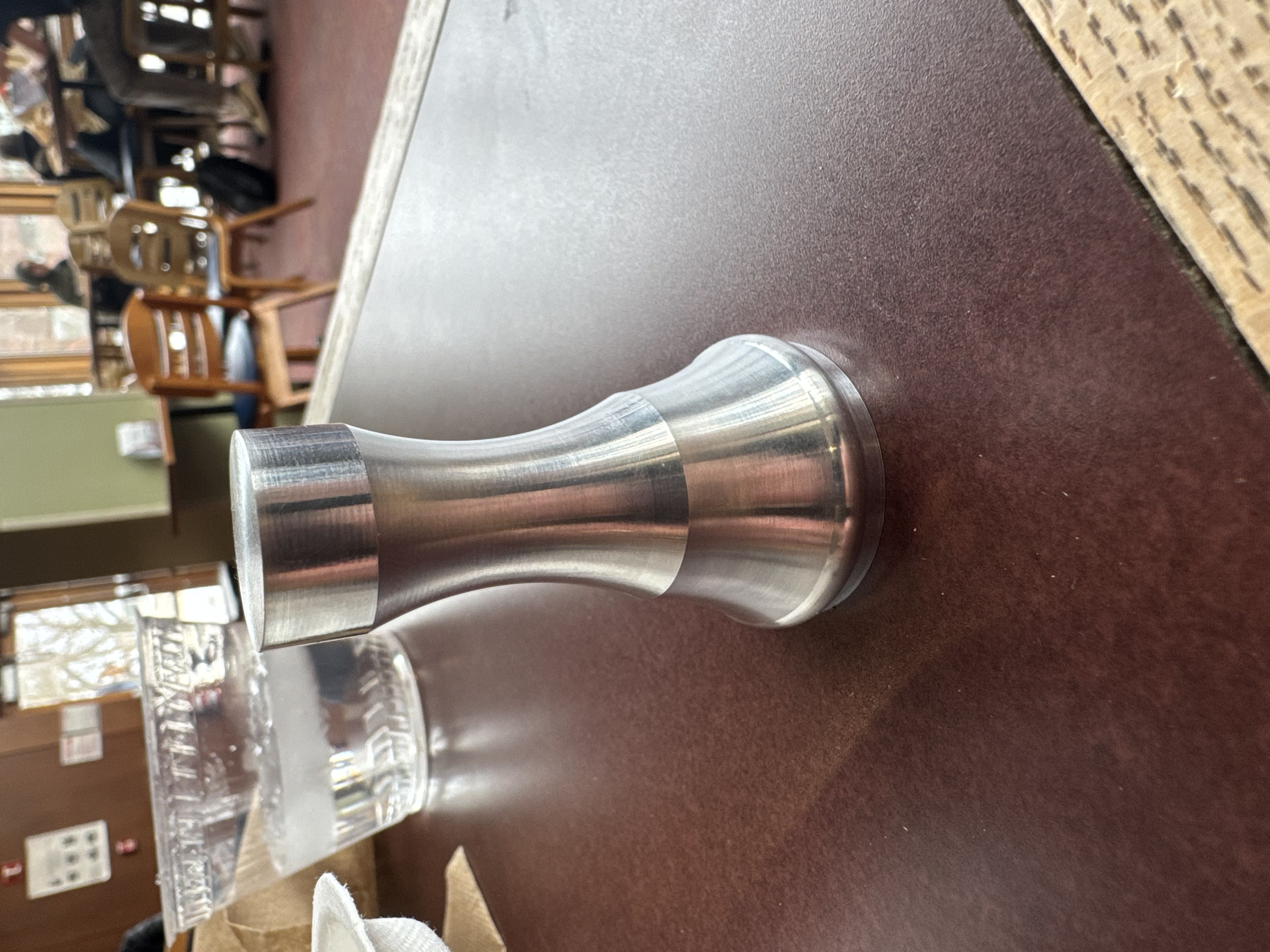
My first CNC lathe part.
Assorted machined parts from BLIMS project.
Sometimes you gotta do what you gotta do to machine fiberglass airframes in the shop safely.